Intro to Technical Cameras
This blog post will explore how lenses and sensors interact geometrically. Camera sensors are rectangular but lenses are cones that project an image circle onto the sensor plane. The relationship between the image circle and the camera sensor is what makes a technical camera different from the your average camera.
Camera Frustums and Image Circles
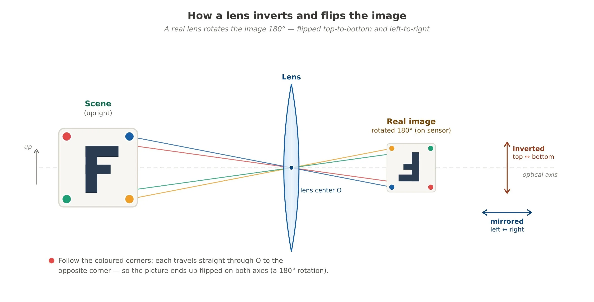
Just a quick refresher from my previous blog post about the Thin Lens Equation, a lens projects an image upside down and backward onto the camera sensor. You don’t need to understand the full physics behind it. The important thing to know is it happens and your camera inverts and flips it for you when displaying or saving it.
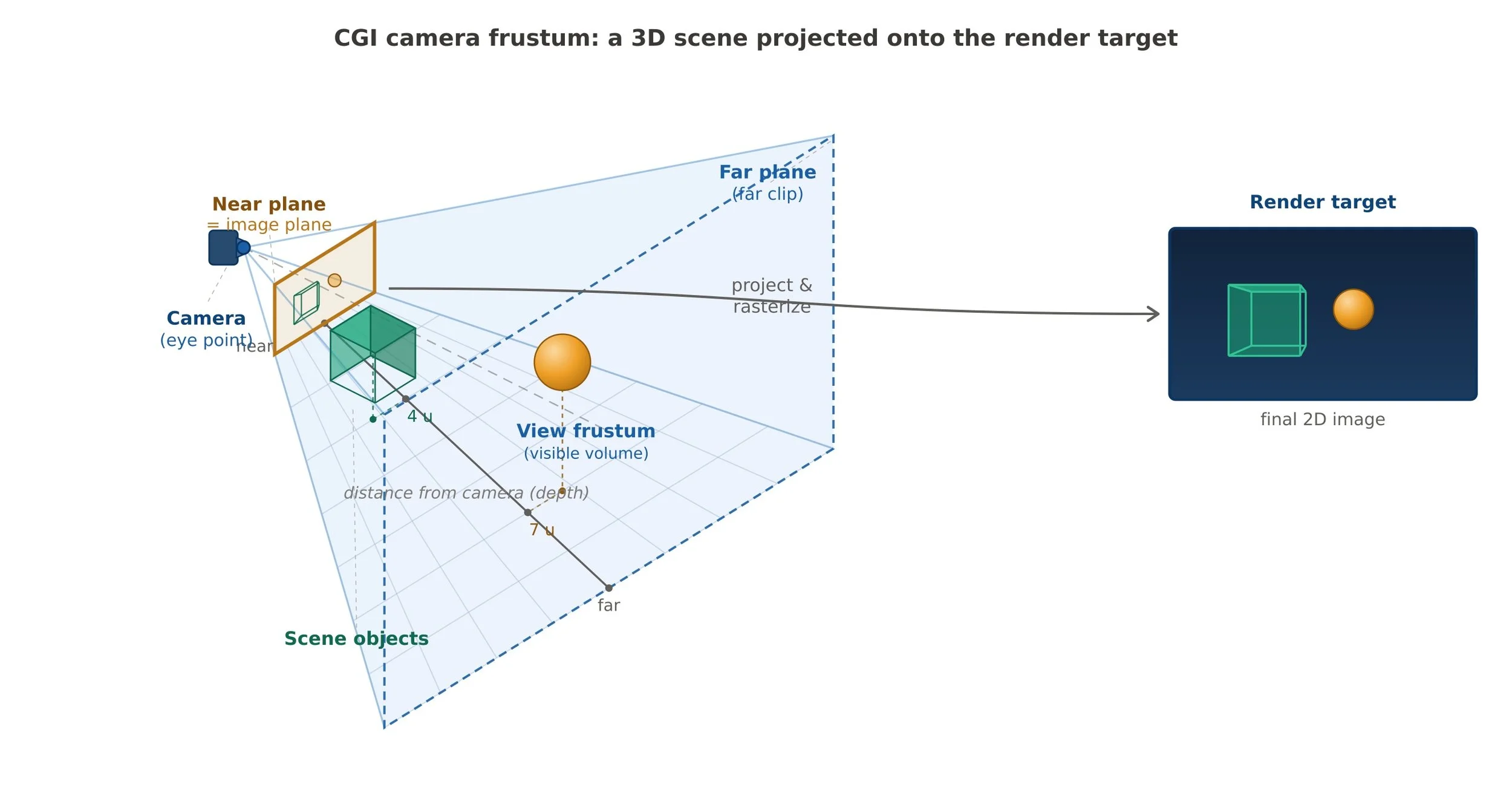
Both computer graphics and real world cameras have a rectangular volume that represents what the camera sees. This is called a camera frustum. A frustum is a 6 sided trapezoidal volume that extends from the camera location in 3d space and extends out to the far plane distance (infinity for physical cameras). The image below is a simple representation of a frustum and the resulting projected image. The small plane at the back is analogous to the camera sensor. In computer graphic terms, that is called the render target, the place that projected pixels are written to.
Camera Frustum in computer graphics
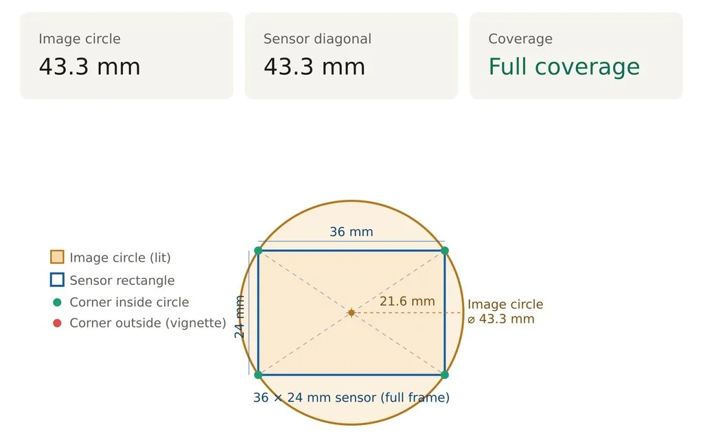
Wait a minute…lenses are round not trapezoidal volumes. So how does this work? Pretty simply. A lens projects an image circle onto the camera sensor. This image circle must completely inscribe the sensor rectangle or you will get a lack of image in the corners (vignetting). Pythagoras tell us that the minimum diameter of the image circle must be the same length as the diagonal of the camera sensor. The image below shows the minimum image circle needed to cover a 35 mm (full frame) camera sensor.
This is a simple view of a lens’ image circle. There’s a lot more going on as lenses have light fall off, chromatic aberration toward the edges, loss of sharpness, and so on. The important bit to note is that the image circle dictates the area your camera sensor can sample from. So what becomes possible if your image circle is larger than the sensor? First, the quality of the image automatically improves when evaluated edge to edge of the image. The reason is that a larger image circle has a larger sweet spot covering more of the sensor with the sharper area.. Second, you now have latitude to sample from different areas of the image circle. This is exactly what 35 mm tilt/shift lenses do and explains why they cost more: more glass to cover a larger image circle and are more complicated to build. By shifting the lens, you change the area that is projected onto the camera sensor (see the image below). Shifting is used to control perspective for objects that are larger than can be normally viewed from a given camera height. For instance, a tall building would require you to tilt the tripod up to capture everything. The act of doing that creates perspective distortion where parallel lines now appear to converge. By shifting the lens down (remember the image is inverted), you can capture more of the building while keeping the lines parallel.
As you can see from the animation, the sensor is capturing different areas of the image circle as it moves around. (If the animation is not happening, try on desktop instead of mobile.) This is the key difference of a technical camera from a full frame one. All technical cameras have lenses that have much larger image circles than what is needed to cover the sensor. Because the image circle is larger, shifting becomes the norm and not the exception. Being able to control perspective is why you see architectural photographers gravitate to technical cameras. When resolution and accuracy matter, you can’t beat a system that shifts to keep all of your lines perfectly parallel and at the highest quality. Yes, you can perspective correct an image after that fact in Photoshop, but that image will be subpar to an image captured via shift. To correct the image, lots of sampling occurs and sampling means blending pixels which results in image quality loss. I know many of you are thinking “Well, it’s good enough” but I will do a blog post in the future that shows why sampling is antithetical to image quality. Friends don’t let friends use Photoshop to sample and interpolate across their images…unless the image quality loss is what the photographer is going for.
What is a technical camera?
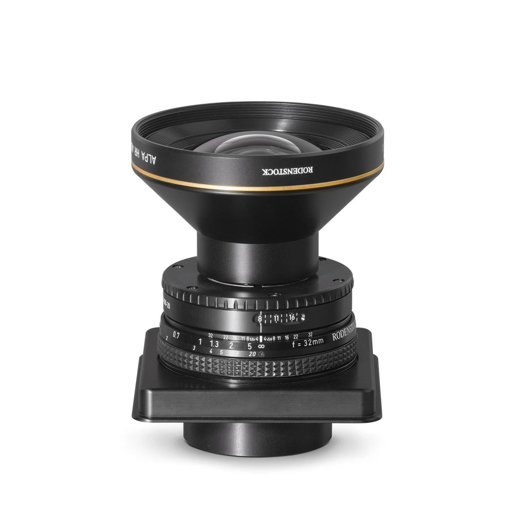
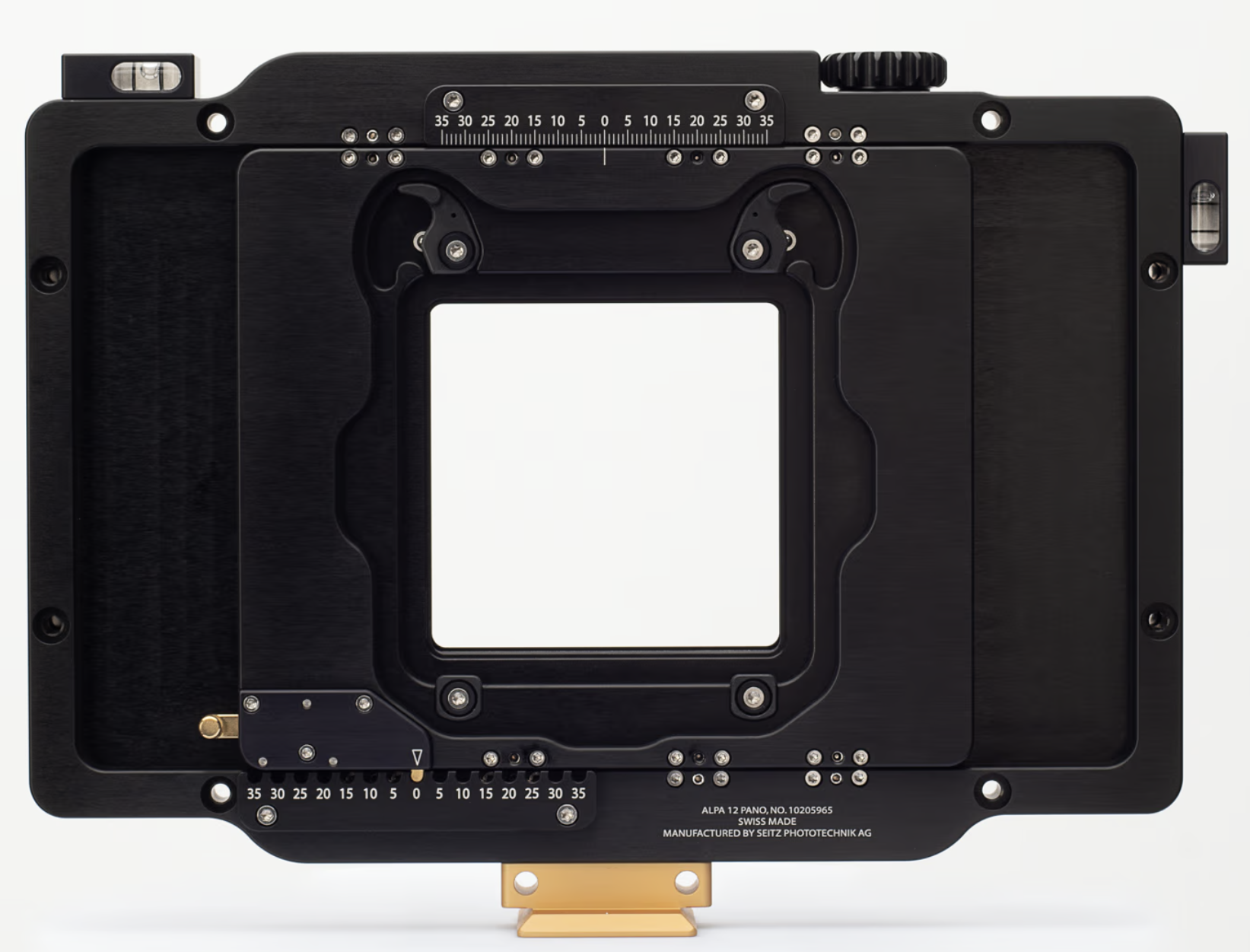
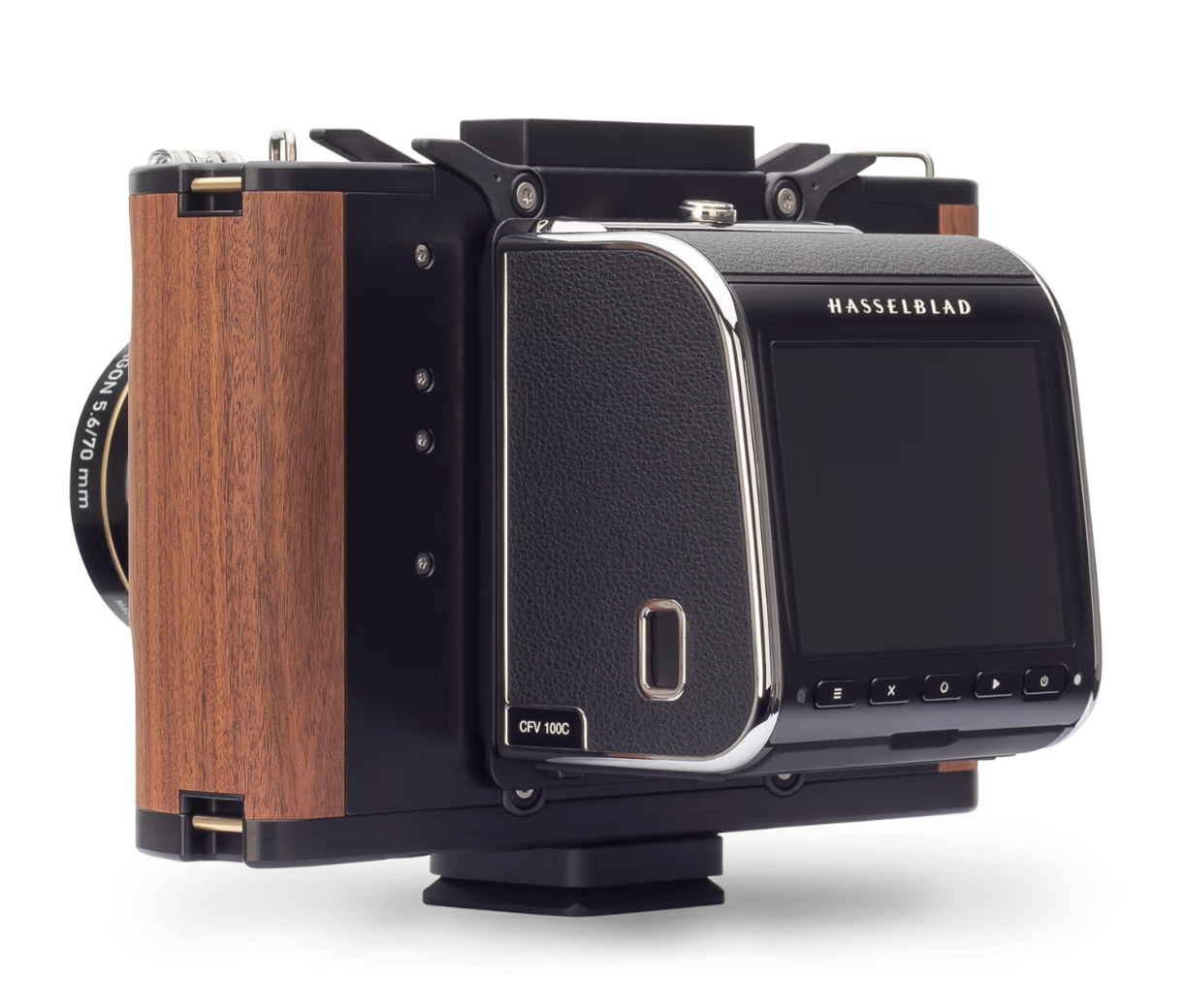
In the old days, cameras were composed of 3 parts: a lens, a view camera, and a sheet of film. A technical camera is a hybrid of the old view camera and the (D)SLRs & mirrorless of the modern era. It has 3 parts: a lens, a camera body with movements, and a film or digital back. DSLRs and mirrorless cameras fuse the body with the digital back. This is easiest for the consumer to use and understand but lacks the flexibility and future proofing of technical cameras, where you can switch between different digital (or film) backs using the same lens and body setup. The images below show the 3 parts of a technical camera.
But I shoot landscapes, not architecture
IMO, landscape photography is an ideal type of photography for a technical camera. I mentioned that shifting is used for perspective control, but if you revisit the animated diagram, the fact you can sample from multiple parts of the image circle means you can create seamless panoramic images at very high resolution. By shooting a series of images using the movements between shots, you can create perfectly planar panoramic shots which are even sharper than nodal point stitched panoramas. Below are 3 shots taken using the Alpa 12 Pano camera (middle above). They are straight out of camera with no adjustments made. Below those is the stitched and finalized image from them. One thing to remember is that because the image is reversed by the lens, the leftmost image was taken with the digital back shifted to the right and the rightmost was all the way to the left. Brad Kaye from Capture Integration suggests that you shoot placing the digital back to the right first, then center, and finally to the left. This results in images that appear in your software in the order you see below.


As you can see from the 3 panels that make up the final image, using a planar camera system means you don’t need as much overlap as you would need using a mirrorless camera with a nodal point setup. This was a simple 3 shot. If I wanted even more of the scene, I could have done a 6 panel shot where I shift the lens up by 10 mm before doing the 3 horizontal shifts, followed by moving it down 20 mm (net 10 mm) and shooting the next 3 images. Shooting this way on medium format backs allows for the ultimate in image resolution. Some photographers extend this even further, yielding giga pixel resolutions for billboard sized prints.
Ok, now I want to try one
Both Alpa Cameras and Phase One Cameras have workshops available to be hands on with their technical cameras before you take the plunge into purchasing one. They are a great way to travel to a great location and try out gear you might not have easy access to. I have been on workshops with both companies’ products and have to say it’s a great experience.
To try out a Phase One XT technical camera, you can go on one the workshops listed here. I went on the western Greenland workshop which was a great experience. Both leaders of the group are knowledgeable and fun to be around.
I use the Alpa 12 Pano camera. They make a series of different cameras with different amounts of shifting movements available. To try one or more of those cameras out, you can go on an Alpa Escape, linked here. I have been on one to Olympic National Park and one in Carmel where the images above were shot. Again, you’ll get expert training on the equipment from people that are genuinely great to be around.